
Leak Testing Quick Disconnect Couplings and Connectors for Data Centre Liquid Cooling
Quick disconnect coupling leak testing verifies that a coupling holds its rated fluid in both of the states it operates in: open, joined to its coupling mating half, and closed, relying on its internal valve. In production this is done by placing the coupling in an evacuated chamber, charging it with helium and measuring any helium that escapes with a mass spectrometer. Because a coupling has more potential leak paths than almost any other component in a liquid cooling loop, and because the consequence of a leak is coolant above live electronics, the systems we build test every unit, not a sample.
This guide covers the coupling types used in data centre liquid cooling, what makes each one difficult, and what a test system has to do to prove them. It sits alongside our wider work on HVAC and data centre cooling leak testing.
Why the coupling is the hardest part of the loop to test
Most attention in a liquid cooling loop goes to the cold plate. It sits directly on the processor, it has the finest internal channels, and it's the part everyone pictures when they imagine a leak. But a cold plate is a sealed assembly with a fixed geometry. Once brazed or welded, its leak paths don't move.
A coupling is different. It's a mechanism. It has moving parts, dynamic seals, a valve that opens and closes, and it's designed to be taken apart and put back together hundreds of times over its service life. It has to seal when it's open, seal when it's closed, and survive the transition between those two states without shedding coolant.
We've engineered, manufactured and commissioned multiple coupling leak test systems that are still running in serial production today, and almost everything in this guide comes from what those programmes taught us rather than from a datasheet. Behind that sits over 30 years of production leak testing, 1,600 machines built and installations in 20 countries.
Anatomy: four things that must all be leak tight
A quick disconnect coupling is usually described as two halves, but for testing purposes it's four things. And the systems we build test one half of the coupling at a time rather than the two halves together.
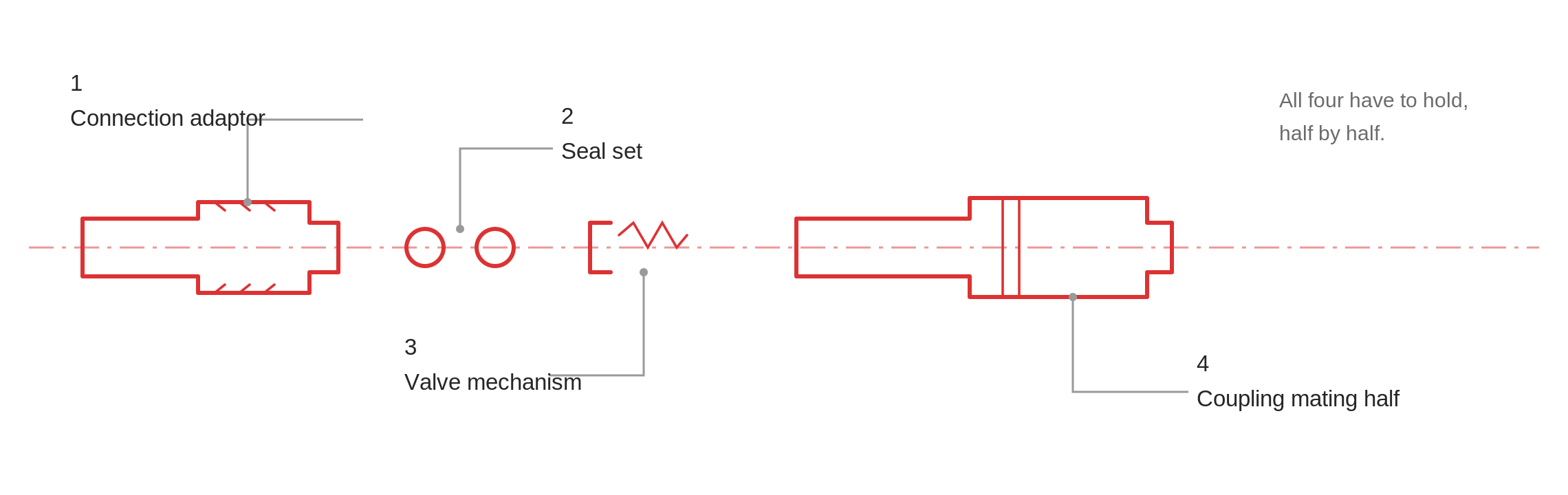
The connection adaptor.
The part that joins the coupling to the hose or pipe behind it, in male and female versions. Its body has to be sound, and so does its joint to the pipework. Crimped, brazed and threaded joints all fail differently.
The coupling mating half.
The half that carries the latching mechanism. More internal geometry, more machined features, more places for porosity to hide.
The seal set.
O-rings and face seals doing two different jobs: sealing the joint between the halves when the coupling is open, and sealing each half internally when it's closed. A seal that's fine at rest can leak under the side load that a real installation puts on it.
The valve mechanism.
In a dry-break or dripless coupling, each half contains a valve that closes as the halves separate. This is the part that's easiest to miss, because it only does its job in the state most test rigs never look at.
All four have to be sound, and each one is proved by testing the half it belongs to. Testing sub-components on the bench and assuming the assembled half is sound is how leaks get through.
The two states: open and closed
This is the single most important idea in coupling testing.
Open.
The seal path runs through the joint between the halves. Coolant is flowing. What you're proving is that the interface holds under pressure, and that neither body has a leak path to atmosphere.
Closed.
Each half relies on its own internal valve to hold its contents. Nothing should drip. In a data centre this happens during hot-swap servicing, with the rack live and hardware around it running.
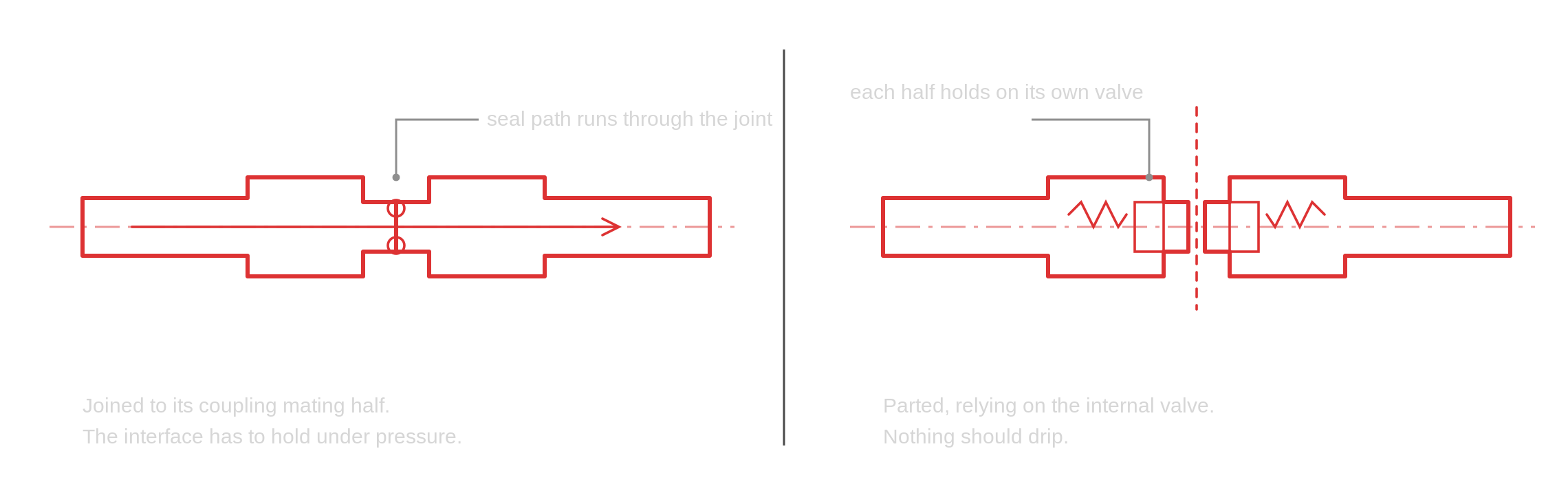
A test that only proves one state has proved half the product. A coupling can be perfectly tight open and still weep from a valve seat when closed, and that failure will only show up in the field, during maintenance, in the worst possible place.
How a coupling has to be tested
The systems we build test one half of a coupling at a time. A half goes into the chamber on its own, it's tested open and then closed, and a measured leak rate is recorded against each state. That's what gives you a result you can defend: not a single verdict on an assembly, but a value against each half, in each of the states it has to hold.
Within the cycle there are always two helium tests, low pressure first and then high pressure. We've seen this requested by more than one customer, so it's best treated as an industry expectation rather than a special case.
Every machine we design and manufacture is built to a CPK of 1.67, so the test itself isn't the source of variation in your data.
Where couplings sit in the cooling loop
Different positions in the loop impose different requirements.
Server to manifold.
Small couplings, opened and closed manually or automatically as servers are serviced. This is where the majority of open and close events happen, so cycle counts are high.
Cold plate to piping.
Inside the server, connecting the cold plate into the loop. Space-constrained, often awkward to fixture.
Manifold to CDU.
Larger bore, higher flow, bigger seal areas. Fewer cycles, but far more coolant behind the seal, so the consequence of failure is larger.
Within the CDU.
Service connections and internal pipework, sized for the full system flow.
The coupling family
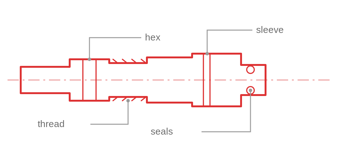
UQD couplings.
The Open Compute Project's Universal Quick Disconnect standard, defined so that couplings from different manufacturers interoperate. Sizes are specified, as is interface geometry. If you're building to OCP, the test has to reflect the standard's requirements rather than your own convention, and fixturing has to handle each size in the range.
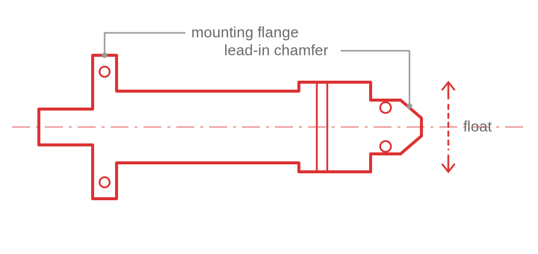
UQDB blind-mate couplings.
The blind-mate variant, designed to connect automatically as a sled is inserted, with a tolerance allowance for misalignment. Hot-pluggable and drip-free on both sides when closed. This is the highest-growth architecture in the sector because it suits GPU sled designs, and it's the hardest to test properly, because the whole point of the component is that it performs under imperfect alignment. A test that only proves it in perfect alignment hasn't proved much.
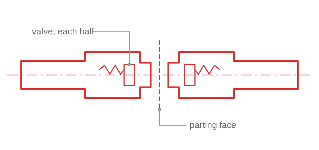
Dry-break and dripless connectors.
Now effectively standard in data centre cooling. The defining feature is the valve mechanism in each half. Testing has to cover the connection adaptor, the coupling mating half, the seals and the valve, half by half.
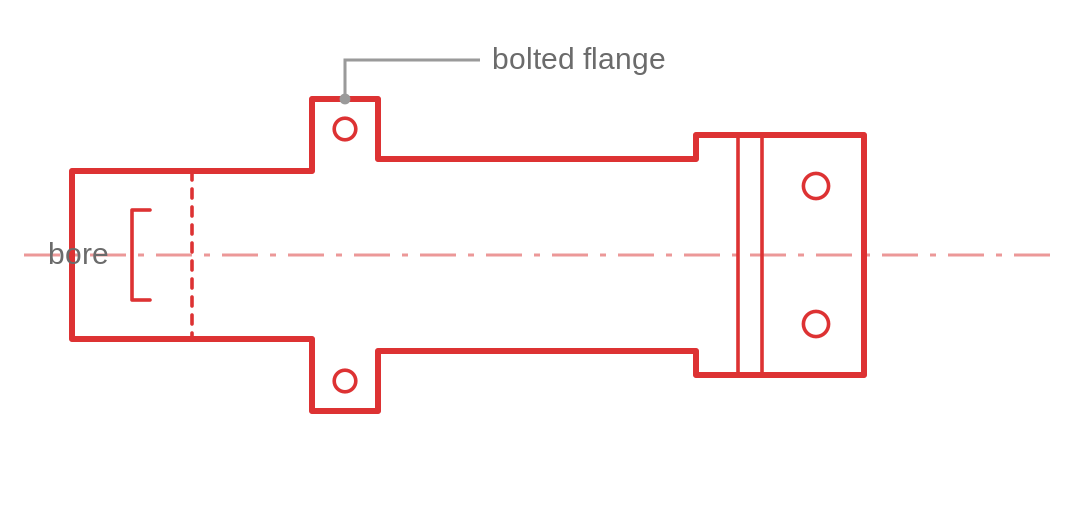
Large-bore manifold and CDU couplings.
Currently up to 2 inch, which fits our existing chambers. 2½ inch is coming, and up to 4 inch has been indicated for the future. High flow, larger seal areas, considerably more mass to handle, and different fixturing economics: the tooling is bigger, the chamber is bigger and the evacuation time is longer.
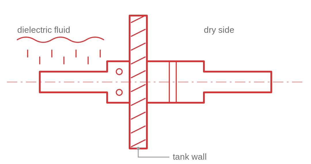
Immersion cooling fittings.
Tank fittings, connectors and ancillaries for immersion systems. An emerging architecture with its own sealing challenges.
Liquid tight is not gas tight
A coupling described as liquid tight has been proven to hold liquid. That's a genuine and useful claim, and it isn't the same as proving it holds gas.
Water has a comparatively large molecule and high surface tension. It won't pass through a leak path that helium moves through easily. So a component can pass a water test, pass a pressure decay test, and still have a leak path that lets vapour and gas through over months in service.
Whether that matters depends on your specification. If the loop is sealed, if it operates over years without top-up, or if the coolant can migrate as vapour into an electronics enclosure, then it matters.
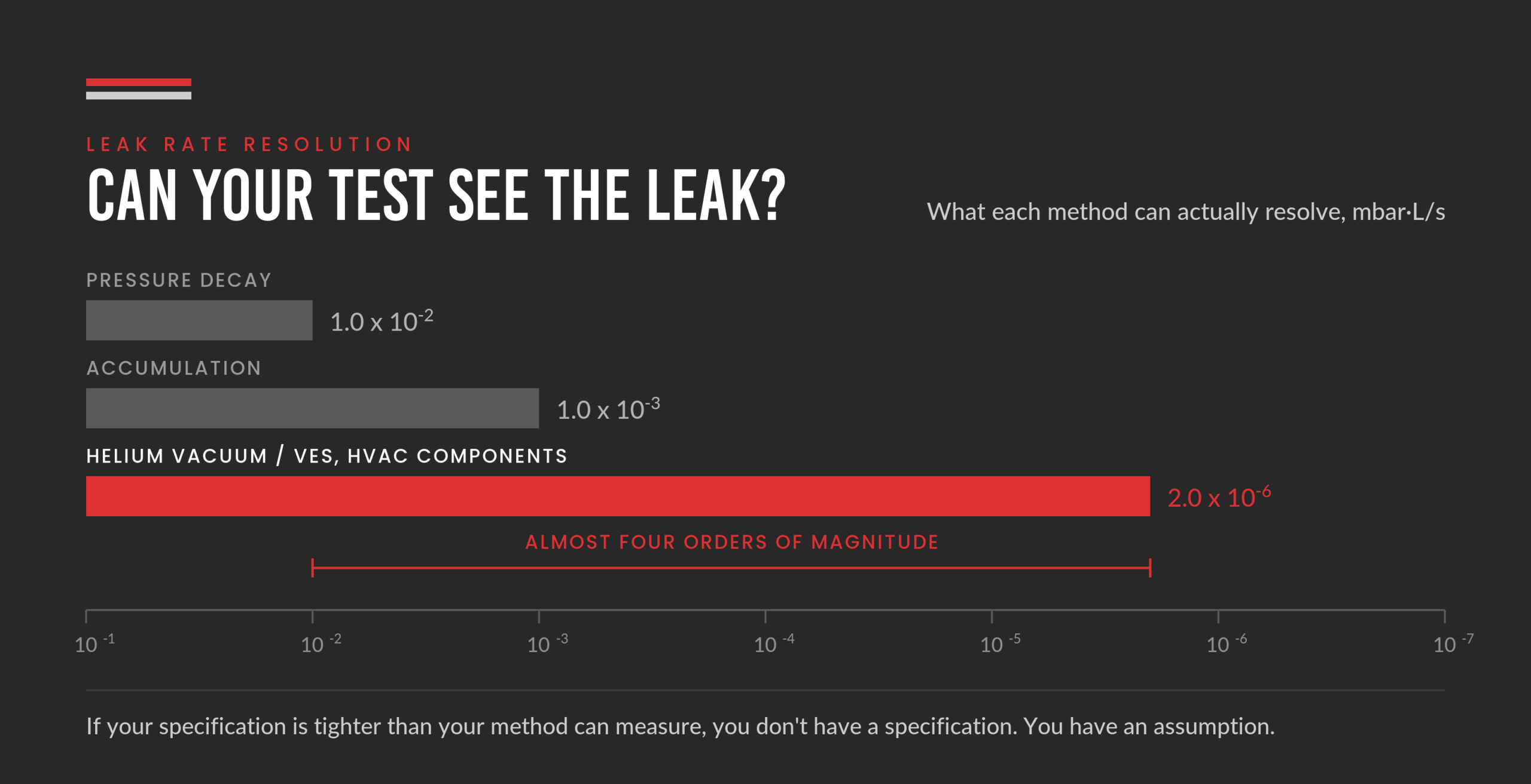
The practical point is about resolution. A pressure decay test resolves to around 1.0 x 10⁻² mbar·L/s. Accumulation testing, with helium or hydrogen tracer gas at atmosphere and no vacuum chamber, resolves to around 1.0 x 10⁻³ mbar·L/s. Neither can verify a specification set several orders of magnitude tighter. A method that cannot see the leak will return a pass, and that pass is not evidence.
Helium vacuum testing resolves down to the rates that liquid cooling specifications actually call for; on HVAC components our systems take testing to 2.0 x 10⁻⁶ mbar·L/s. It gives a clear pass-fail result, with a measured leak rate value. Below the pass-fail limit that value is measured. Above it the test stops, so the value is predicted rather than measured.
If you're setting or reviewing a specification, our leak rate calculator is a quick way to convert between units and check that a method can actually resolve the rate you've written down. Our helium leak testing guide covers the underlying method in more detail.
Why 100 per cent testing rather than sampling
Sampling manages risk when the consequence of an escaped defect is proportionate and recoverable. Neither applies here.
A coupling that leaks in a rack puts coolant onto live hardware. The cost isn't the coupling, it's the downtime, the hardware and the customer's confidence. And because couplings are consumable, service items opened and closed repeatedly, a batch defect can propagate across a data hall before anyone notices.
That's why the systems we build test every unit, not a sample. Recording the result against a serial number also gives you something sampling never can: if a question is raised about a batch two years later, you can answer it with data rather than an argument.
Testing couplings in production
The laboratory question is whether the coupling is tight. The production question is whether you can prove it on every unit, at rate, without the test becoming the bottleneck.
One thing to be clear about early: there's no generic coupling test. Tooling is bespoke to the coupling, because the fixture has to seal against that geometry, actuate that particular mechanism, and hold the part without distorting it. That's why couplings can't simply be sent out to a test house, and why tooling design is a substantial part of the engineering rather than an accessory to it. It's also the part that repays early conversation, because the tooling concept usually settles what the cycle time can be.
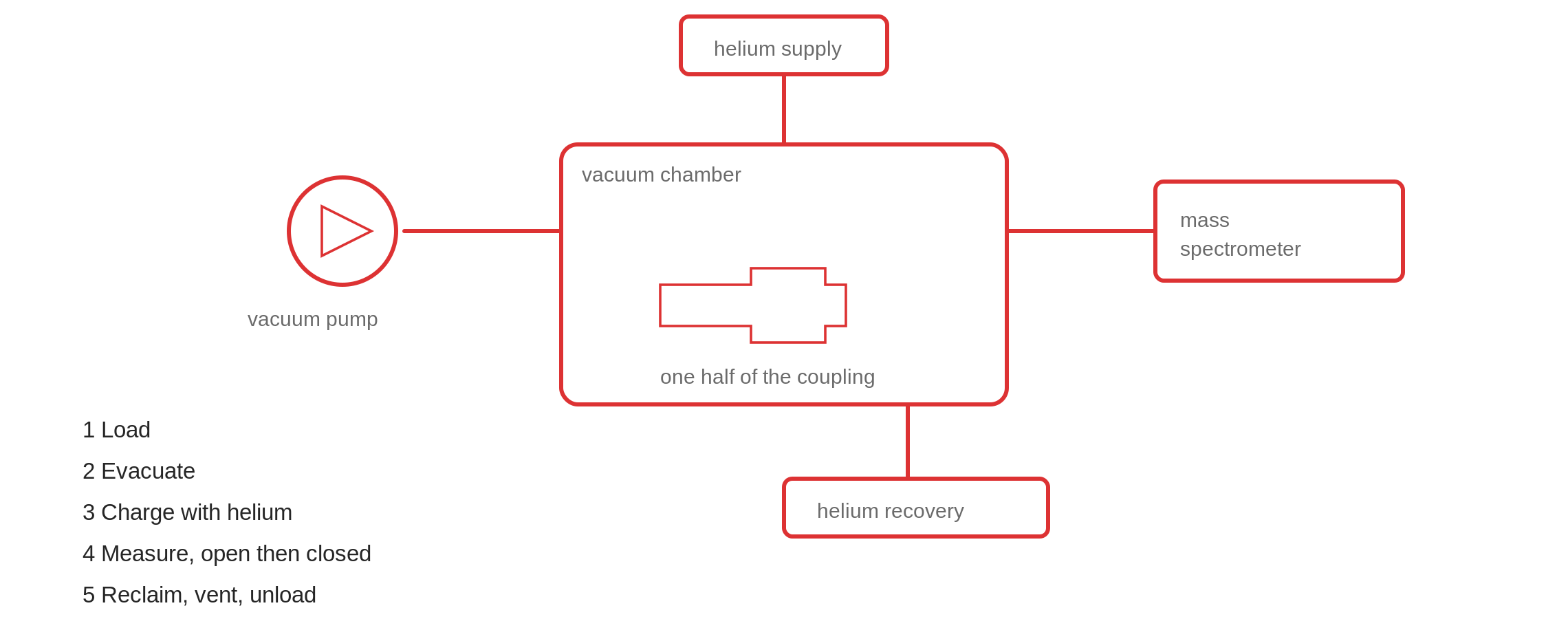
The cycle.
Load, seal the chamber, evacuate, charge with helium, measure open, measure closed, reclaim the helium, vent, unload. Each of those steps takes time and each is a candidate for optimisation.
Gross leak and fine leak together.
A part with an obvious defect will flood a chamber with helium and cost you a long recovery before the next test. Screening for gross leaks first, in the same station, protects cycle time and protects the instrument.
Handling the family.
Very few manufacturers build one coupling size. The platform has to accept the whole range, and it has to be error-proofed so an operator physically can't run the wrong programme on the wrong part. Poka-yoke tooling isn't a nicety here; a mixed-size line without it will eventually pass an untested part.
Multi-pressure testing.
Some specifications require proof at more than one pressure. Doing that in one clamping, rather than as separate operations, keeps the cycle the same.
Helium recovery.
Helium prices have risen 30 to 40 per cent in recent years and supply is volatile. Charging and reclaim can be integrated into the test system so the gas is recovered rather than vented. On a high-volume coupling line, this materially changes the cost per part. Our helium leak testing systems page covers how that integration is built.
Cleanroom considerations
Coupling and cold plate manufacture is moving towards cleanroom conditions, and that constrains the test system. Where a system has to operate in an ISO Class 6 environment we specify dry vacuum pumps in place of oil-sealed pumps, which removes the need to carry fresh and used oil in and out of a clean area.
Cleanroom-specific design, manufacturing, cleaning and certification requirements are assessed separately for each installation rather than assumed.
What good looks like
If you're specifying a coupling leak test system, these are the questions worth asking:
- Does it prove both states, open and closed, with a measured leak rate recorded against each?
- Does it test each half of the coupling in turn, rather than inferring the result from bench checks on sub-components?
- Can it resolve your specified leak rate with margin, and does it give you a number?
- Does it screen for gross leaks before the fine leak test?
- Does the tooling cover your whole coupling family, error-proofed?
- Does the cycle fit inside your takt, including load and unload?
- Does it record a result against every serial number?
- Does it recover helium rather than vent it?
- Can it integrate with your line without rewriting machine PLC logic?
- If you're in a cleanroom, is the pump specification compatible?
Frequently asked questions
One half at a time. The half is placed in a sealed chamber, the chamber is evacuated and the half is charged with helium. A mass spectrometer measures any helium that escapes. Each half is tested open and then closed, and a measured leak rate is recorded against each state.
There's no universal figure; it depends on the coolant, the operating pressure, the service life and the consequence of failure. What matters is that the method can resolve the specified rate with margin. A specification set tighter than the test method can measure isn't being verified.
Because it seals differently in each. Open, the seal path runs through the joint between the halves. Closed, each half relies on its internal valve. The systems we build test one half of the coupling at a time, taking each half in turn and recording a measured leak rate against it. A coupling can be tight in one state and leak in the other, and a test that only covers one state has only proved half the product.
By Andrea Whittle CEng MIMechE, Chief Engineer at Vacuum Engineering Services. Andrea has over 30 years in production leak testing and is a Certified Machinery Safety Expert and a Certified Expert in Functional Safety.