Helium Leak Testing Systems by VES
World-renowned helium leak detection expertise, with over 1,600 systems deployed globally for automotive, HVAC, clean energy and industrial manufacturing applications.
Precision Helium Leak Testing for Automotive, HVAC and Clean Energy Sectors
What Is Helium Leak Testing?
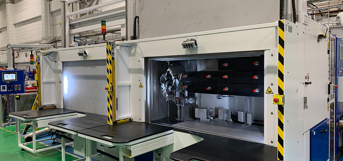
Helium Leak Testing Systems for Production Environments.
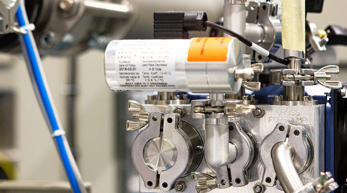
Helium leak testing is a highly sensitive method of detecting leaks in components, assemblies and production parts. Helium is used as a tracer gas because it is inert, non-toxic, light and detectable at very low leak rates.
In manufacturing environments, helium leak testing systems help verify product integrity, protect safety-critical components and support quality assurance across sectors such as HVAC leak testing systems, automotive, clean energy, hydrogen and medical manufacturing.
VES designs and builds helium leak testing systems around the product, required leak rate, production volume, cycle time and test method, helping manufacturers achieve reliable results in real production conditions.
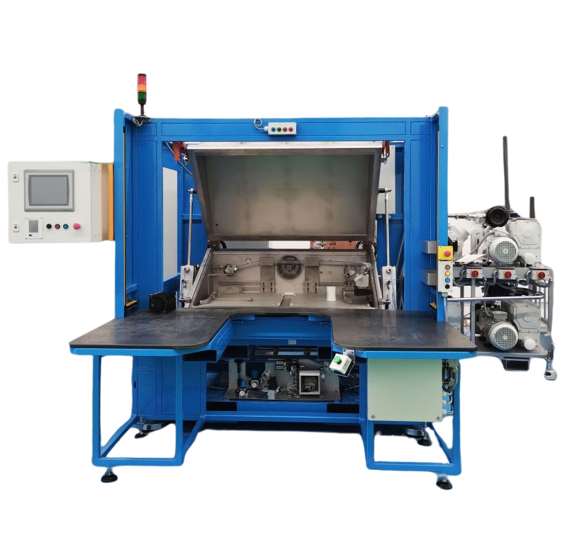
Custom Leak Detection
Engineered for precision and reliability, our Custom Helium Leak Testing Machines deliver outstanding sensitivity, repeatability, and durability
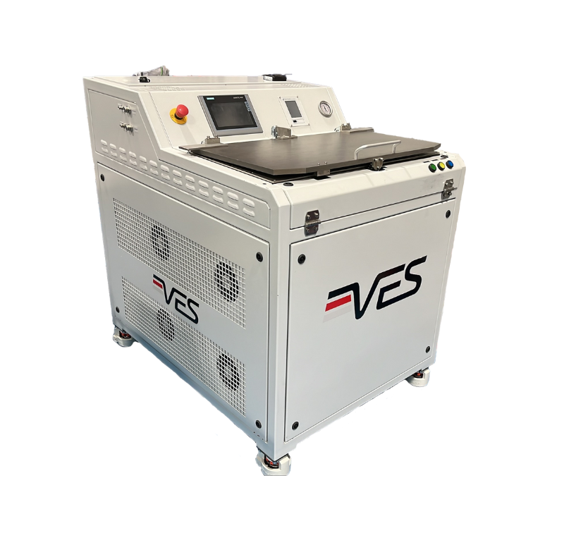
OptVol Leak Detection
OptVol is a compact, all-in-one helium leak testing solution. Capable of detecting leaks as small as 5.0e-06 mbarL/s,

Accuro Leak Testing
Accuro is a high-performance mass spectrometry leak testing system designed to work without a vacuum setup.
Comprehensive Helium Leak Testing Systems
Explore VES helium leak detection systems for production environments, from high-sensitivity hard vacuum chambers to accumulation, sniffer, spray and automated leak testing methods designed around the part, leak rate, cycle time and production process. For deeper technical background, read our helium leak testing guide.
Whether you're leak testing fuel tanks, HVAC parts, or medical devices, our technologies include hard vacuum systems, cost-effective accumulation testing, pinpoint sniff detection, and strategic spray methods. Each tailored for precision and reliability.
Cost-effective and chamber-free, accumulation testing uses helium as a tracer gas under atmospheric pressure. Ideal for detecting medium-to-small leaks with repeatable accuracy, it's a perfect upgrade from air-under-water and pressure decay methods.
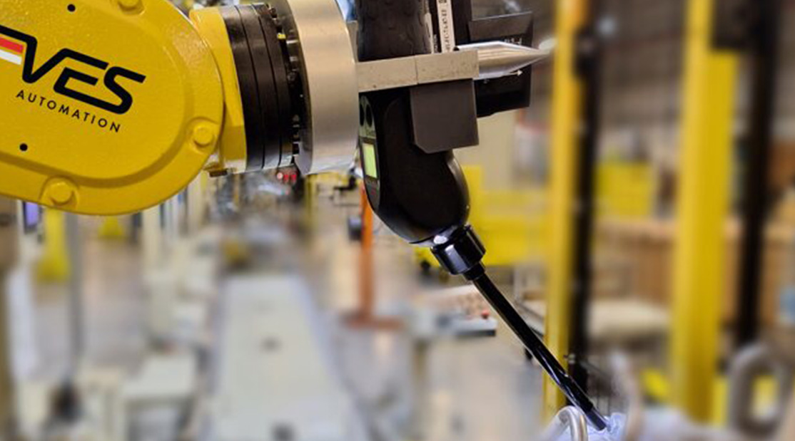
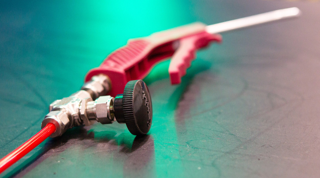
Best for large or complex parts, sniff testing locates helium leaks directly using a handheld or robot arm-held probe. It's ideal when pinpointing and repairing leaks is essential — especially when full chamber testing isn't practical.
Designed for evacuated parts, helium spray testing strategically exposes components to helium to detect areas of potential ingress. A reliable choice for parts requiring absolute barrier integrity under vacuum conditions.
Reducing Helium Cost and Waste
Helium is an effective tracer gas, but it is also a valuable resource. For manufacturers using helium leak testing systems at scale, gas cost, availability and sustainability can become important parts of the business case.
VES can support helium-efficient test strategies through system design, gas management and PURE helium recovery systems. PURE helps manufacturers recover, repurify and reuse helium from suitable leak testing processes, reducing waste while helping maintain test integrity.
For connected support, VES also provides calibration services and clean energy test expertise including hydrogen testing systems.
Frequently Asked Questions
Find quick answers to common questions about our helium leak testing systems, methods, and applications.
Speak to a Helium Leak Testing Specialist
Get personalised guidance for your leak testing challenges.

Customers