We’ve spent a long time around leak test systems built for couplings, and the thing that still surprises people is how much of the risk sits in a component most specifications treat as a fitting.
A cold plate gets the attention. It sits on the processor, it has the finest internal channels, and it’s the part everyone pictures when they imagine coolant reaching electronics. But a cold plate is a sealed assembly with fixed geometry. Once it’s brazed or welded, its leak paths don’t move.
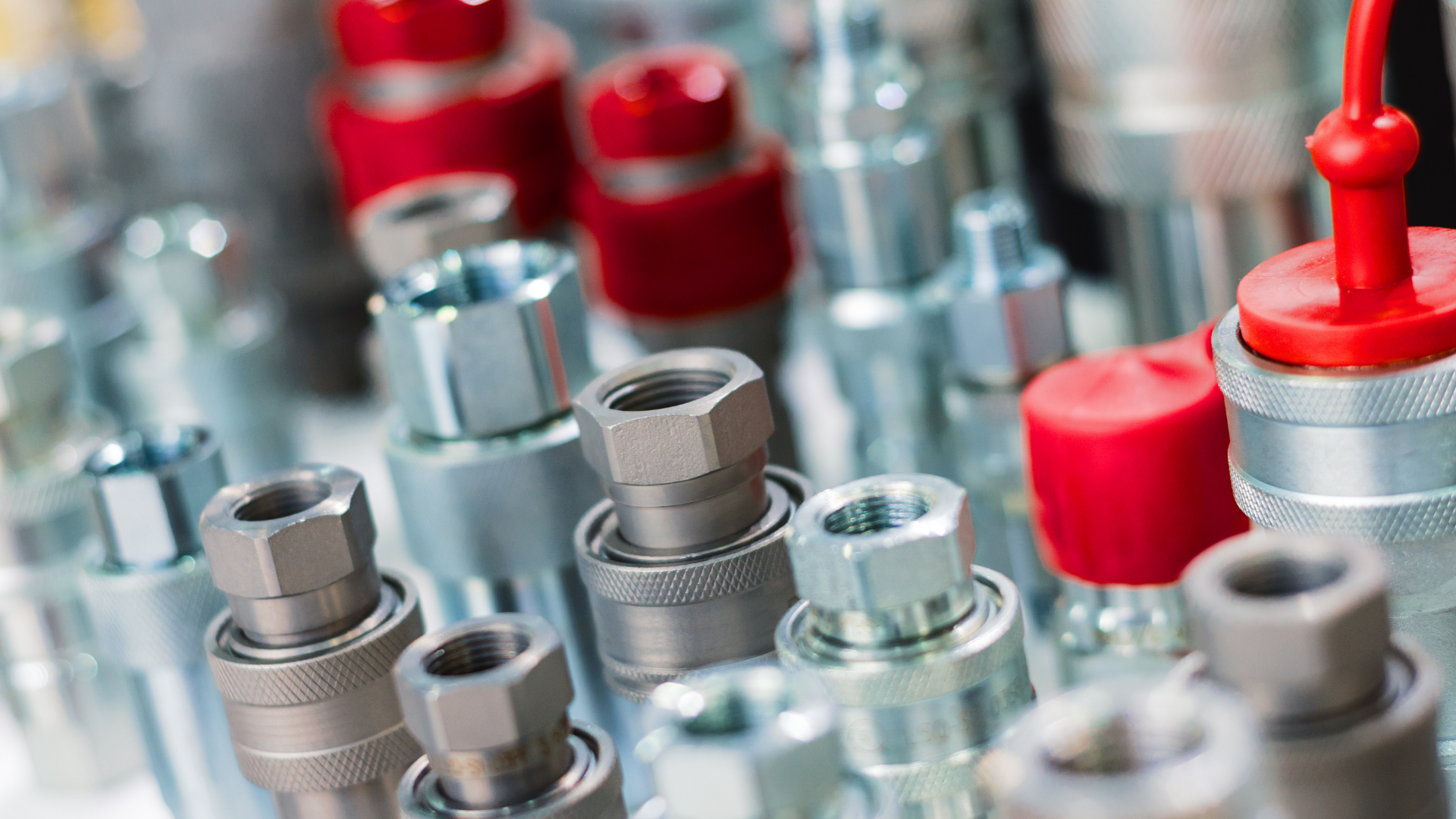
A quick disconnect coupling is a mechanism. It has moving parts, dynamic seals and a valve that opens and closes, and it’s designed to be taken apart and put back together hundreds of times across its service life.
That’s a different testing problem, and it’s worth being precise about why.
Four things, not one
For testing purposes a coupling isn’t two halves. It’s four things that all have to hold.
The connection adaptor. The fitting that takes the coupling onto the hose or pipe, in male or female form depending on the design. Its body has to be sound, and so does its joint to the line behind it. Crimped, brazed and threaded joints each fail in their own way.
The coupling mating half. The half it mates with, usually carrying the latching mechanism. More internal geometry, more machined features, more places for porosity to hide.
The seal set. Two jobs rather than one: sealing the joint between the halves when the coupling is open, and sealing each half internally when it’s closed. A seal that’s perfectly good at rest can leak under the side load a real installation puts on it.
The valve mechanism. In a dry-break or dripless coupling, each half contains a valve that closes as the halves separate. This is the one most often missed, because it only does its job in the state most test rigs never look at.
Two states, and most regimes only prove one
Open, the seal path runs through the joint between the halves and coolant is flowing. What you’re proving is that the interface holds under pressure and that neither body has a leak path to atmosphere.
Closed, each half relies on its own internal valve to hold its contents. Nothing should drip. In a data centre that state happens during hot-swap servicing, with the rack live and hardware around it.
A test that only proves one state has proved half the product. A coupling can be perfectly tight open and still weep from a valve seat when closed, and that failure will only show up in the field, during maintenance, in the worst possible place.
This is the observation I’d most want a design engineer to take away: the two states fail differently, and they fail for different reasons.
How a coupling has to be tested
The systems we build test one half of a coupling at a time. A half goes into the chamber on its own, it’s tested open and then closed, and a measured leak rate is recorded against each state.
That’s what gives a result you can defend. Not a single verdict on an assembly, but a value against each half, in each of the states it has to hold.
Within the cycle there are always two helium tests, low pressure first and then high pressure. We’ve seen that requested by more than one customer, so it’s best treated as an industry expectation rather than a special case.
Where the specification usually goes wrong
A coupling gets specified as liquid tight. That’s a real claim and it can be proven. Water has a comparatively large molecule and high surface tension, and it won’t pass through a leak path that helium moves through easily.
So the part passes, and it can still have a path that lets vapour through over months in service.
The practical point is resolution. A pressure decay test resolves to around 1.0 x 10⁻² mbar·l/s. Accumulation testing, with helium or hydrogen tracer gas at atmosphere and no vacuum chamber, resolves to around 1.0 x 10⁻³. Neither can verify a specification set several orders of magnitude tighter. A method that can’t see the leak will return a pass, and that pass isn’t evidence.
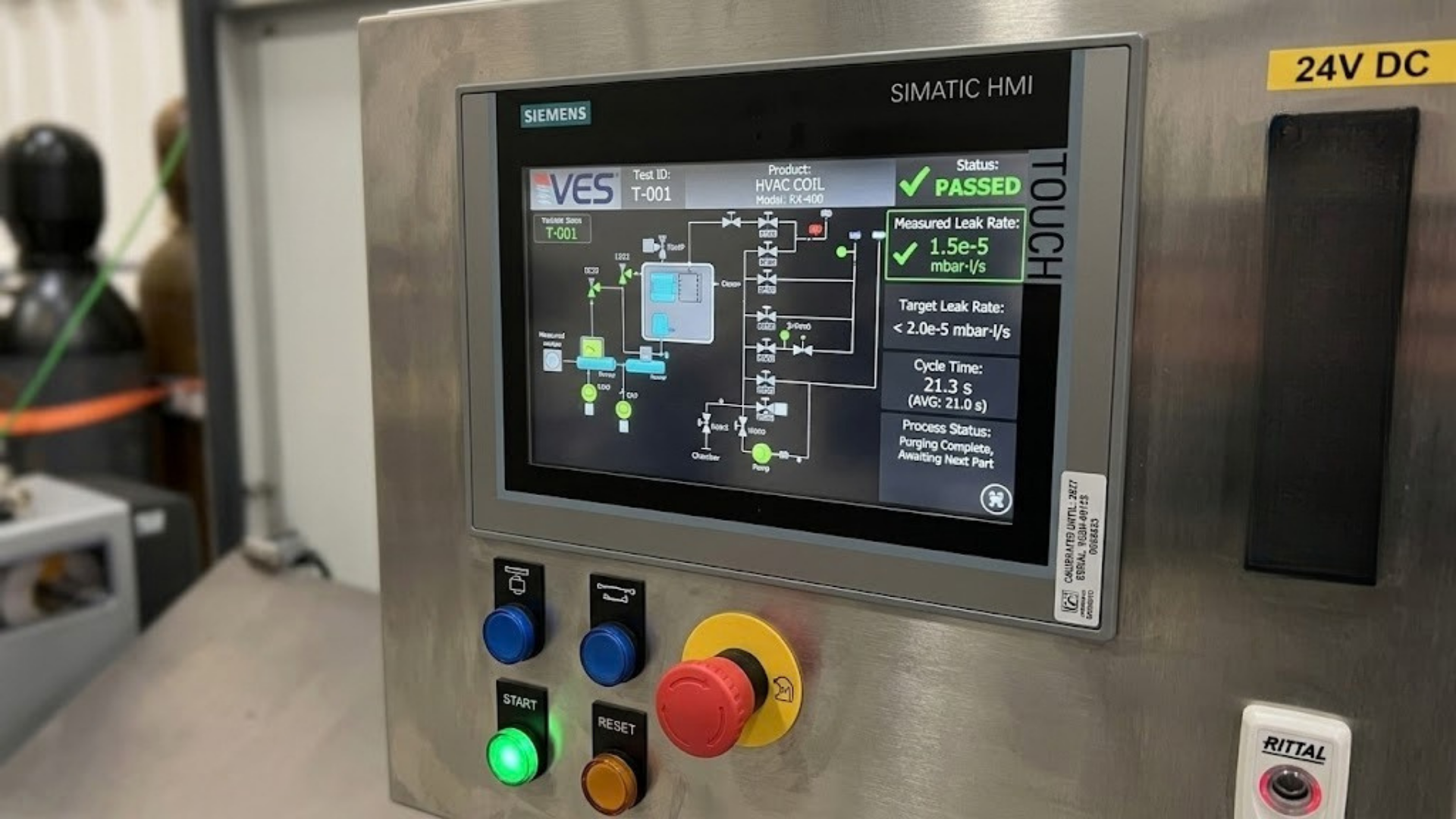
helium leak testing in a vacuum resolves down to the rates liquid cooling specifications actually call for. On HVAC components our systems take testing to 2.0 x 10⁻⁶ mbar·l/s, and it gives a clear pass-fail result with a measured leak rate value alongside it.
One thing that can’t be outsourced
There’s no generic coupling test. Tooling is bespoke to the coupling, because the fixture has to seal against that geometry, actuate that particular mechanism and hold the part without distorting it.
That’s why couplings can’t simply be sent out to a test house, and why the tooling design is a substantial part of the engineering rather than an accessory to it. It’s also the part that repays an early conversation, because the tooling concept usually settles what the cycle time can be.
The full guide covers each failure mode, both states, the coupling family from UQD through to large bore, and what a production test has to do to catch them: