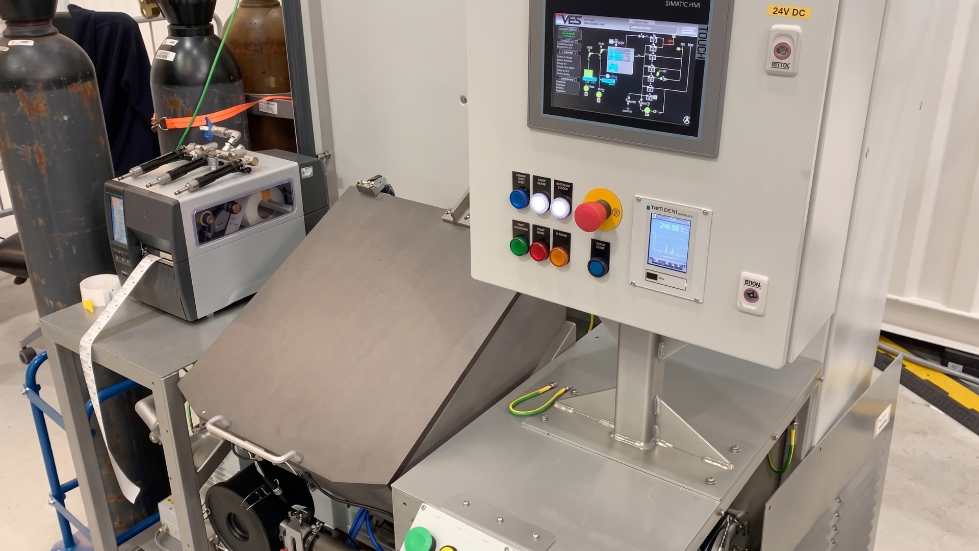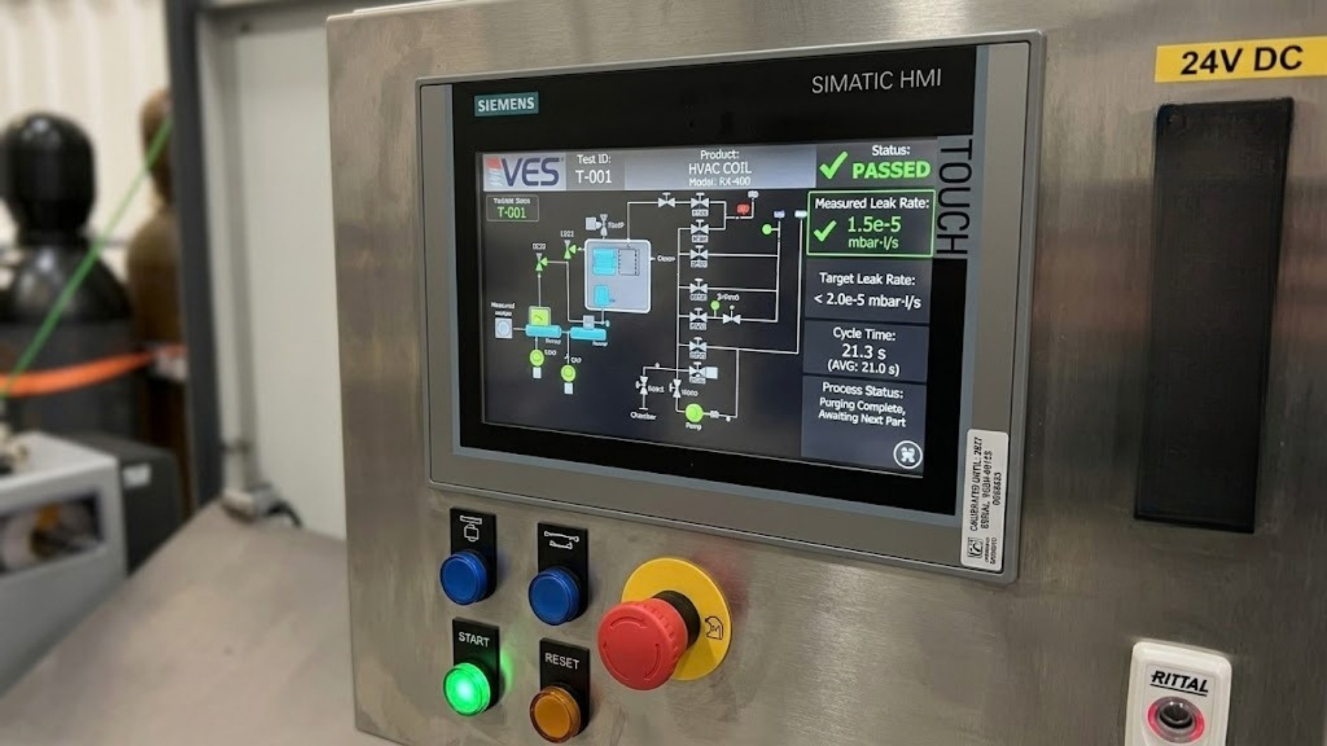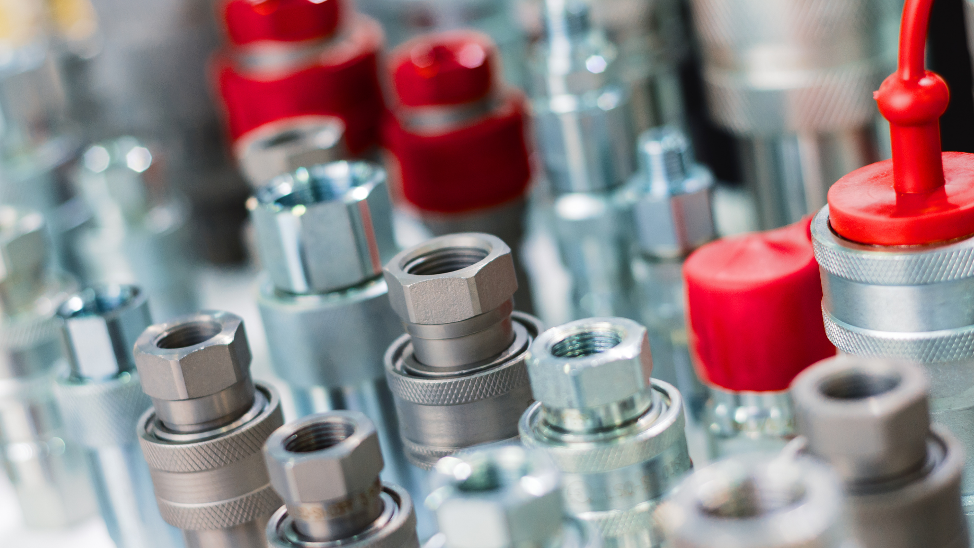
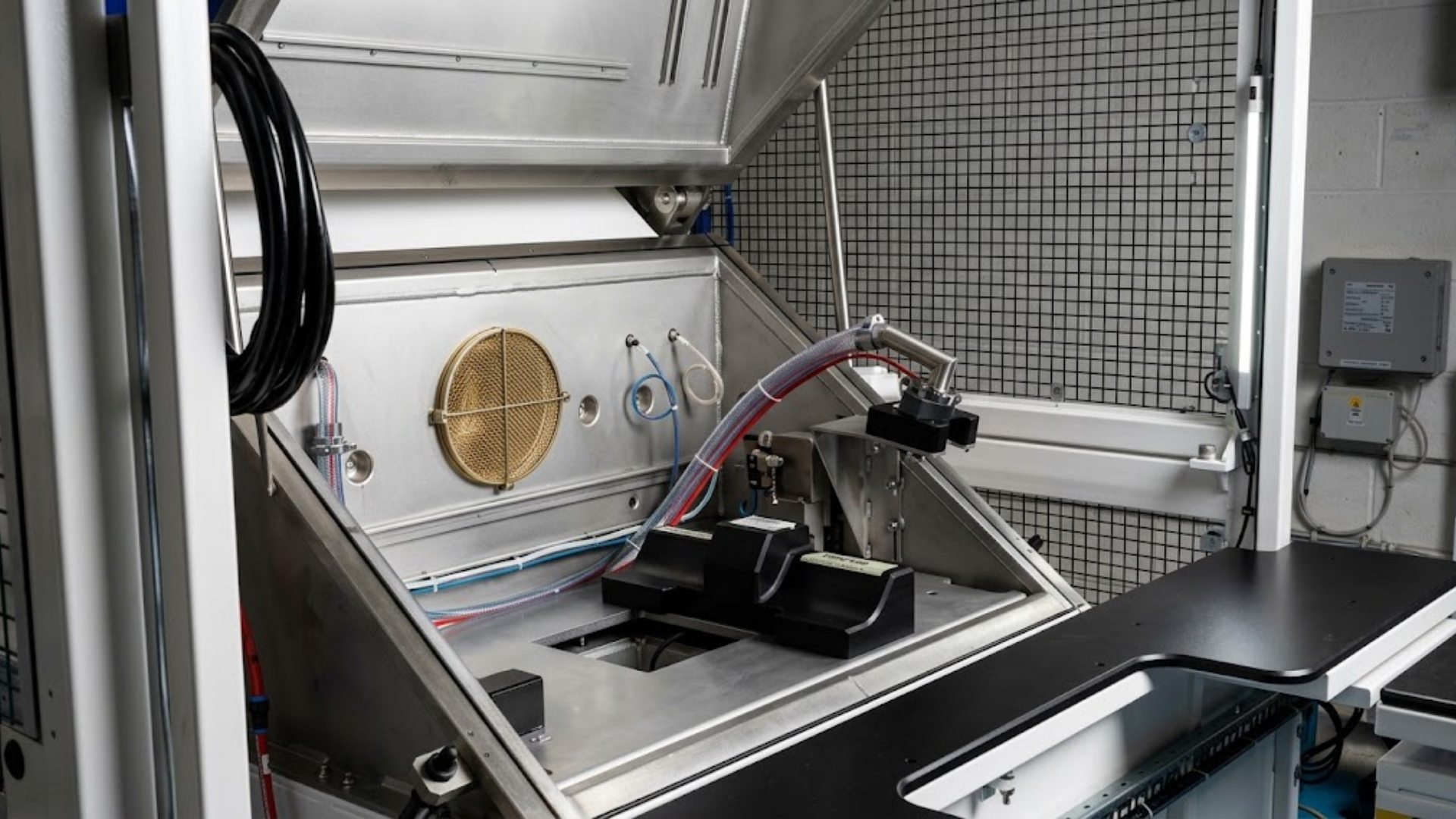
UQD couplings are leak tested one half at a time, in a helium vacuum chamber, with the half proved open and then closed and a measured leak rate recorded against each state. What makes the UQD range different from a one-off coupling test is that the standard defines a family, and a manufacturer building across that family needs a test platform that handles all of it rather than one rig per size.
This piece covers what the standard specifies, what each size asks of the test fixture, and why the tooling question decides most of the rest.
What the UQD standard is for
The Universal Quick Disconnect standard comes out of the Open Compute Project. Its purpose is interoperability: couplings from different manufacturers are specified so they mate correctly, with the sizes and interface geometry defined rather than left to each supplier.
For a manufacturer, that changes what the test has to prove. You aren’t only demonstrating that your coupling is sound. You’re demonstrating that it’s sound against a published interface that someone else’s hardware will connect to.
That’s a subtle but important shift. If you’re building to the standard, the test has to reflect the standard’s requirements rather than your own internal convention, and the fixturing has to handle each size in the range on those terms.
Testing the range rather than the part
The UQD family spans several sizes, and the practical problem is that very few manufacturers build only one of them.
Six sizes with six separate test rigs is rarely a sensible answer. It’s six sets of tooling to maintain, six calibration routines, six sets of spares and six opportunities for a part to end up in the wrong fixture.
A platform that accepts the family instead needs three things.
Tooling that covers the range. The fixture has to seal against each geometry in turn, actuate each mechanism, and hold each part without distorting it. Tooling is bespoke to the coupling, so covering a family means designing for the family from the start rather than adapting a single-size fixture later.
Error-proofing across the changeover. An operator physically shouldn’t be able to run the wrong programme on the wrong part. On a mixed-size line, mechanical keying that makes the wrong combination impossible is worth considerably more than a screen prompt.
A changeover that people will actually follow. A theoretically correct procedure that takes fifteen minutes will get shortcut on a busy shift. The changeover time is a design input, not an afterthought.
The blind-mate variant
The blind-mate version of the standard is designed to connect automatically as a sled is inserted, with an allowance for misalignment. It’s hot-pluggable and drip-free on both sides when closed.
It’s also the hardest of the family to test properly, and the reason is worth understanding.
The whole point of a blind-mate coupling is that it performs under imperfect alignment. A test that only proves it in perfect alignment hasn’t proved much. What you want to know is whether it still seals when it’s presented slightly off-axis, which is how it will actually be used.
That’s a fixturing problem more than a measurement problem, and it’s the one I’d want settled early in a project rather than discovered at commissioning.
Where UQD couplings sit in the loop
The UQD format is built around the manual server-to-manifold connection, which is the joint a technician makes and breaks by hand during service.
That service pattern is why the closed state matters so much for this family. A coupling that’s opened and closed repeatedly across its life, in a live rack with hardware around it, has to hold on its internal valve every single time, not just on the day it was tested.
What good looks like
For a UQD programme, these are the questions worth asking of a test system:
- Does it prove both states, open and closed, with a measured leak rate against each?
- Does it test each half in turn rather than inferring from bench checks?
- Does the tooling cover your whole size range, error-proofed against the wrong combination?
- For blind-mate parts, does the fixture present the coupling as it will actually be used, including misalignment?
- Does it resolve your specified rate with margin, and give you a number?
- Does the changeover fit the way the line actually runs?
- Does it record a result against every serial number?
Frequently asked questions
How are UQD couplings leak tested?
One half at a time in a helium vacuum chamber. The half is tested open, where the seal path runs through the joint between the halves, and then closed, where it relies on its internal valve. A measured leak rate is recorded against each state.
How is a blind-mate coupling tested differently?
The difference is in the fixturing rather than the measurement. Because the coupling is designed to work under imperfect alignment, the fixture needs to present it the way a sled would, including a degree of misalignment, rather than only in perfect alignment.
Can one system test the whole UQD size range?
Yes, with tooling designed around the family from the start and error-proofing that prevents the wrong programme running on the wrong part. Because tooling is bespoke to each geometry, the range has to be understood at the design stage rather than added later.
What leak rate should a UQD coupling be tested to?
That depends on the coolant, the operating pressure, the service life and the consequence of a failure. The more useful question is whether your test method can resolve the rate you’ve specified. Pressure decay resolves to around 1.0 x 10⁻² mbar·l/s; on HVAC components our helium vacuum systems take testing to 2.0 x 10⁻⁶.
What about larger couplings?
Large-bore manifold and CDU couplings are currently handled up to 2 inch, which fits our existing chambers. Two and a half inch is coming, and up to 4 inch has been indicated for the future. Larger bores mean higher flow, larger seal areas, considerably more mass to handle and different fixturing economics.